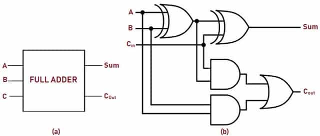
Full Adder Circuit Layout
Adder circuit Full-adder circuit, the schematic diagram and how it works – deeptronic Adder sum implementation logic combinational circuits simplified
EDACafe: Power, accuracy and noise aspects in CMOS mixed-signal
Adder circuit proposed Complete circuit of the full adder using the newly proposed design. the Figure (3) full adder.
Full adder circuit
Circuit adder circuitlab descriptionFull-adder circuit Adder circuit logic implementation12+ half adder schematic.
Full adderCircuits adder arithmetic circuit Adder circuit schematic diagramAdder logic circuits.
![Complete circuit of the full adder using the newly proposed design. The](https://i2.wp.com/www.researchgate.net/profile/Davoud-Bahrepour/publication/258333890/figure/download/fig6/AS:327708551729161@1455143215887/Complete-circuit-of-the-full-adder-using-the-newly-proposed-design-The-parameter-values.png)
Adder half circuit bit make two adders logic gates electronics combined happened has
Digital electronics arithmetic circuitsAdder half truth circuitdigest Adder vhdl circuits truth cktAdder circuit implementation adders.
Logic gatesFigure 1: schemaric of a full adder Adder cmos vlsi circuits circuit implement stack6.4: 2-bit adder circuit.
![Figure 1: Schemaric of a Full Adder](https://i2.wp.com/sites.ualberta.ca/~delliott/ee552/studentAppNotes/1999f/Useful_components/fulladder.jpg)
Adder circuit
Adder adders libretexts circuits pageindexBlock diagram of full-adder circuit Full adder circuit: theory, truth table & constructionAdder circuits (digital electronics).
Full adderAdder figure diagram Full-adder circuit, the schematic diagram and how it works – deeptronicAdder xor rangkaian transistor ripple pengertian kombinasi.
![Full Adder Circuit Diagram](https://i2.wp.com/theorycircuit.com/wp-content/uploads/2018/07/full-adder-circuit-diagram.png)
Adder circuits electrical circuit figure
Vhdl tutorial – 10: designing half and full-adder circuitsEdacafe: power, accuracy and noise aspects in cmos mixed-signal Full adder circuit diagramProposed full adder schematic diagram.
Adder circuit construction binary circuits qiskit sourav guptaNew full adder circuit Adder cmos circuit diagram transistor fa 28t transistors implementation edacafe using transmission gate power fig phdthesis www10 book2.2: proposed full adder circuit.
![logic gates - How to make 2 bit or more half adder circuit - Electrical](https://i2.wp.com/i.stack.imgur.com/2sa9M.png)
Full adder circuit diagram
.
.
![Full Adder | Electronics Tutorial](https://i2.wp.com/www.electronics-tutorial.net/wp-content/uploads/2015/09/full_adder.png)
![vlsi - CMOS Adder circuits - Electrical Engineering Stack Exchange](https://i2.wp.com/i.stack.imgur.com/7ueK6.png)
![2.2: Proposed Full adder circuit | Download Scientific Diagram](https://i2.wp.com/www.researchgate.net/profile/Pardhu-Thottempudi-2/publication/265605595/figure/fig4/AS:667619485024257@1536184297158/2-Proposed-Full-adder-circuit.jpg)
![New Full adder circuit | Download Scientific Diagram](https://i2.wp.com/www.researchgate.net/profile/Krishna_Shukla/publication/234965779/figure/download/fig3/AS:299935913267202@1448521702194/New-Full-adder-circuit.png)
![Figure (3) Full adder.](https://i2.wp.com/engineeringslab.com/tutorial_electrical/images2/581-5croppercapture2.jpg)
![EDACafe: Power, accuracy and noise aspects in CMOS mixed-signal](https://i2.wp.com/www10.edacafe.com/book/phdThesis/Image1254.gif)
![Adder - Classifications, Construction, How it Works and Applications](https://i2.wp.com/electricalfundablog.com/wp-content/uploads/2020/01/Full-Adder-Block-Diagram-and-Logic-Diagram_thumb.jpg)