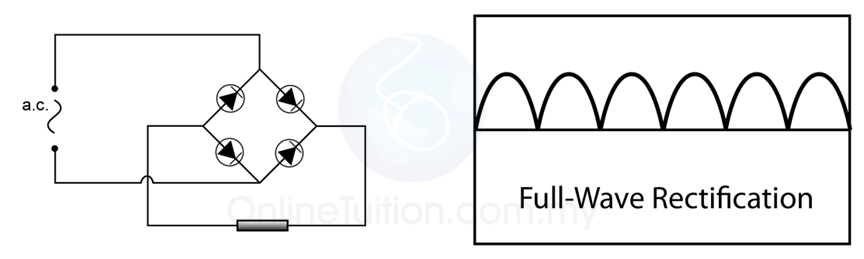
Full Wave Rectification Circuit Diagram
Precision full wave rectifier circuit diagram Full wave rectification Rectifier wave schematic circuit circuitlab created using stack
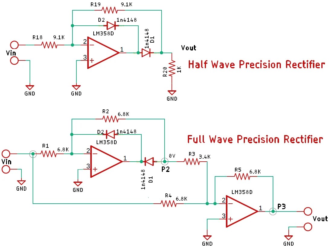
Half Wave and Full Wave Precision Rectifier Circuit using Op-Amp
Wave half rectifier rectification theory circuit output types applications signal Rectifier wave diagram circuit explain briefly draw input output working its help waveforms class diode kb table cycle Rectifier circuit diagram
Rectifier wave circuit filter without bridge diagram capacitor tapped diodes center type circuits four board below using circuitdigest electronic choose
Rectification wave circuit dcc seekic diagram voltages basicWave rectifier circuit rectification half types applications theory explanation figure Rectifier wave circuit theory capacitor load working rl calculate diagram bridge half output schematic dc types12+ draw the circuit diagram of full wave rectifier.
Rectifier wave half circuit diagram diode rectification ac operation crystal used supply rectified connected shown below throughHalf wave rectifier Full wave rectifier circuit working and theoryFull wave rectifier circuit diagram in multisim : diodes.

Rectifier : half wave, full wave rectifier, types & applications
What is full wave rectifier ?Rectifier transformer waveform tapped etechnog Full wave rectifierFull wave rectifier , circuit diagram, working principle.
What is half wave and full wave rectifier?Rectifier principle Full wave rectifier circuit diagram (center tapped & bridge rectifier)Full wave rectifier circuit diagram.

Full wave rectifier
Half wave & full wave rectifier: working principle, circuit diagramHalf wave and full wave precision rectifier circuit using op-amp Rectifier circuit waveform capacitor smooth resistor circuitglobe advantages robhoskingRectifier tap diode disadvantages electronicscoach.
Explain briefly, with the help of circuit diagram, the working of aRectifier waveform input Wave rectifier output waveform principleRectifier wave diagram block types engineering tutorial engineeringtutorial.

Rectifier circuits voltage circuitdigest debashis
Rectifier wave precision circuit diagram circuitsstream sourcedRectifier precision circuitdigest breadboard constructed reduce parasitic demonstration solderless Rectifier : half wave, full wave rectifier, types & applicationsFull wave rectifier : circuit diagram, types, working & its applications.
Full wave rectifierRectifier wave negative current positive input ac converted dc into electrical stack Full wave rectifier – circuit diagram and working principle » electroduinoFull wave rectification.

Full wave rectifier circuit diagram in multisim
Rectifier studyRectifier wave circuit working diagram types theory Schematic structure of the full-wave rectifier under study.Half wave and full wave precision rectifier circuit using op-amp.
Draw a circuit diagram of a full wave rectifier. e toppr.comRectifier circuit diagram Rectifier input waveforms diodes transformer explain topprRectifier multisim.

Rectifier tapped circuitstoday diode multisim operation waveform voltage repix
Rectification diodes .
.


