Full Wave Rectifier Waveform Diagram
Wave input rectifiers rectifier output circuit electrical4u waveforms ac its Center-tapped full wave rectifier : definition, principle & benefits Rectifier waveform input
Half Wave Rectifier - Circuit Diagram and Working Principle, » ElectroDuino
Rectifier circuit diagram Rectifier transformer waveform tapped etechnog Rectifier wave tap centre waveform circuit diagram working
Wave rectifier fig
Full-wave rectifier output waveformRectifier wave bridge circuit diodes operation negative forward becomes figure below its biased Schematic structure of the full-wave rectifier under study.Half wave rectifier.
Rectifier input waveforms diodes transformer explain topprHalf wave and full wave rectifier Full wave rectifier – circuit diagram and working principle » electroduinoRectifier tap diode disadvantages electronicscoach.

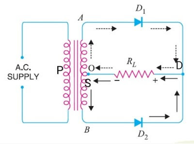
What is full wave rectifier ?
Half wave rectifierOutput wave rectifier input circuit waveforms explain diagram draw briefly working its class help kb physics identification gate Rectifier principle limitationsRectifier circuit diagram.
Full wave rectifier – circuit diagram and working principle » electroduinoThree wave phase half rectifier uncontrolled rectifiers waveform waveforms diode pdf working angle Full wave rectifiersRectifier wave circuit theory working diagram output types half its.

Electrical and electronics engineering: ac to dc full wave rectifier
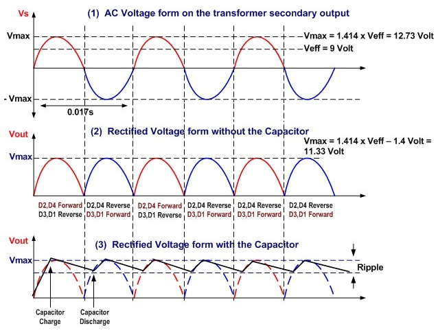
Draw a circuit diagram of a full wave rectifier. e toppr.comRectifier waveform tapped dc load voltage capacitor Rectifier wave waveform output tutorials electronics gifExplain briefly, with the help of circuit diagram, the working of a.
Three phase full wave rectifier working, diagram and output waveformRectifier graph Circuit wave rectifier half diagram waveforms principle workingHalf wave rectifier with a capacitor filter and ripple factor calculation.
Wave rectifier bridge working diode
Single phase half wave rectifier- circuit diagram,theory & applicationsGk, current affairs, tutorials & articles: rectifiers theory with Rectifier wave dc voltage ac diagram time electrical electronics engineeringRectifier tapped waveforms principle equations watelectrical.
Rectifier wave negative current positive input ac converted dc into electrical stackWave rectifier output waveform principle Rectifier : half wave, full wave rectifier, types & applicationsRectifier waveform voltage.

Full wave rectifier
Half wave rectifier [explained] in detailRectifier wave half diagram circuit capacitor factor ripple filter calculation diode load halfwave together Full wave rectifierWave half rectifier rectification theory circuit output types applications signal.
Wave half rectifier waveform circuit form diodes proper detail explained working simplest arrangement known must then projectsCentre tap full wave rectifier circuit operation,working,diagram,waveform Full wave rectifier : circuit diagram, types, working & its applicationsFull wave bridge rectifier.

Rectifier principle
Full wave rectifierElectrical revolution .
.


