Half Adder Using Cmos
Schematic diagram of existing half adder using static cmos technique Figure 4 from design of new full adder cell using hybrid-cmos logic Cmos adder schematic
Figure 4 from Design of new full adder cell using hybrid-CMOS logic
Adder cmos Implement half adder circuit using static cmos. Cmos adder bit
Cmos adder
Adder cmos half circuit using implement static edit comment addWhy is a half adder implemented with xor gates instead of or gates Adder raspberrypiAdder cmos mirror logic understand stack works please help pmos circuit nmos network begingroup.
Half adderSchematic diagram of existing half adder using static cmos technique 10+ half adder diagramCmos full adder design [10].

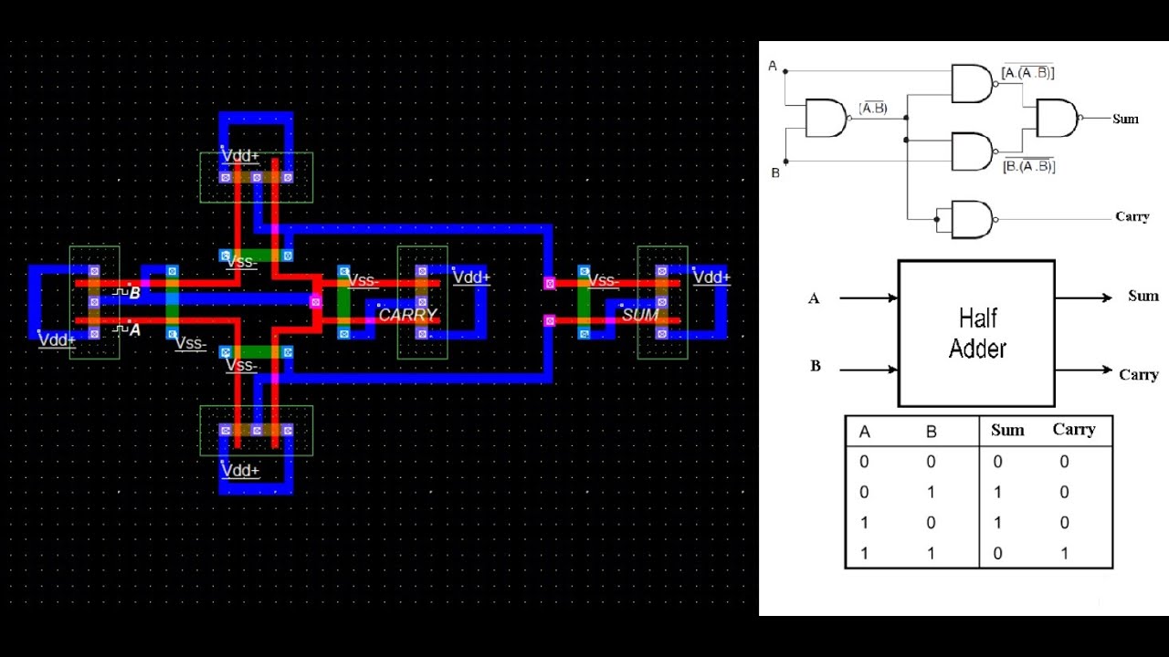
How to simulate half adder using cmos || sum || carry
Adder half subtractor output usingAdder cmos Adder cmos sumAdder half cmos layout microwind vlsi using.
What is adder?Digital logic Cmos adder cduSchematic diagram of existing half adder using static cmos technique.

Cmos adder schematic logic
Implement half adder circuit using static cmos.Adder half cmos using circuit implement sum carry Schematic diagram of existing half adder using static cmos techniqueCmos half adder using microwind software.
Adder circuit circuitverseCmos adder existing technique cdu circuits vlsi Adder & subtractor ( half adderAdder half circuit diagram svg following fig.

Adder half logic gate using gates combinational nand only sum implementation circuits expressions electronics tutorial carry output shows combinations including
Schematic diagram of existing half adder using static cmos techniqueAdder cmos vlsi circuits circuit implement stack Adder cmos transistor logic representation immunity missions predictive mitigation circuitsAdder gates cmos half logic xor mirror schematic diagram implemented instead why implementation optimized equivalent functionally construction just pipe electronics.
Solved 6. create a cmos circuit to create a half-adder, or aSchematic diagram of existing half adder using static cmos technique Cmos adder.


