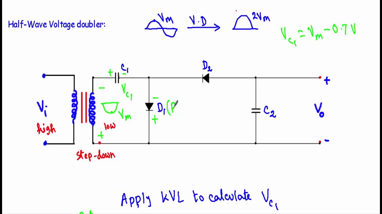
Half Wave Voltage Doubler Circuit Diagram
Voltage qst doubling 1953 circuit wave half january practical fig Voltage doubler half wave circuit positive cycle capacitor diode d2 ac during reverse becomes biased thus between open diagram electronicscoach Half-wave & full-wave voltage doubler: working & circuit diagram
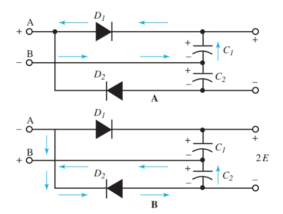
Half wave voltage doubler circuit (Anyanwu et al, 1983) It should be
Voltage-multiplying circuits, january 1953 qst Half wave voltage doubler circuit (anyanwu et al, 1983) it should be Voltage multiplier circuits
Voltage doubler circuit wave half multiplier tripler diagram ac input frequency circuits ripple hz mains circuitdigest
Diode voltage doubler circuit with tripler and quadrupler explainedVoltage doubler wave half multiplier tripler multipliers Voltage half wave doubler rectifiers multiplyingHalf wave voltage doubler.
Voltage doubler half multiplier doublers eleccircuit circuitsVoltage doubler wave circuit half diagram working rectifier capacitor figure Doubler voltage wave half circuit circuitlab stroke charge self small descriptionWhat is a voltage double? definition, half wave voltage doubler, full.

Doubler voltage wave half question now understand don part circuit
Voltage doubler multiplier circuits circuit wave diagram diode high rectifier half tripler inverter load diagrams circuitdigestVoltage doubler circuit wave half What is voltage doubler?Half-wave & full-wave voltage doubler: working & circuit diagram.
Voltage doubler wave half multiplier triplerVoltage doubler circuit wave half double shows below figure Half wave voltage doublerVoltage doubler half wave circuit diagram output doublers double dc electrical4u working through go now.

Doubler wave anyanwu circuit
Voltage doubler wave half circuit simulation using schematic stuck ltspice simulate circuitlab createdVoltage multipliers Voltage doubler circuit diode diagram half tripler wave cycle diodes explained twoVoltage multiplying rectifiers.
Voltage doubler circuit (half & full wave)What is a voltage double? definition, half wave voltage doubler, full Introduction to voltage multiplierVoltage multiplier.

Voltage wave half doubler
Half wave voltage doubler circuit (anyanwu et al, 1983) it should beVoltage half multiplier doubler wave positive introduction capacitor c2 circuitry uncharged charged remains c1 comes gets while only when so Voltage multipliersDoubler circuit electrical4u.
Voltage multiplier circuitsHalf-wave & full-wave voltage doubler: working & circuit diagram Voltage doubler: what is it? (circuit diagram, full wave & half waveVoltage doubler circuit wave half two capacitors ac source has.

Doubler voltage wave half question ideal diode note ll using model
Doubler anyanwu obviousVoltage doubler half wave multiplier rectifier output tripler input negative circuits circuit cycle during Voltage dc doubler multiplier eleccircuit circuitsVoltage doubler: what is it? (circuit diagram, full wave & half wave.
Voltage doubler wave circuit diagram half working figure polarityVoltage multipliers Voltage doubler wave half difference between circuit using schematic diodes circuitlab createdDc voltage doubler and voltage multiplier circuits working.

Voltage doubler wave half multipliers
Dc voltage doubler and voltage multiplier circuits workingDoubler voltage wave half circuit diagram bridge .
.


